
This guide covers the complete Technician workflow — from installing the software and setting up your account, through establishing a remote connection, to completing a diagnostic or programming job.
eLinehub is a pure-software remote automotive diagnostics platform. It maps a Mechanic’s physical VCI — whether USB-based or Ethernet/DoIP-based — directly to your computer as a locally connected device, so your OEM diagnostic software sees it exactly as if the hardware were sitting on your desk. No hardware relay boxes. No remote desktop. The Mechanic is the on-site workshop where the vehicle is located; you are the remote Technician performing the diagnostics.
Step 1: Download and Install
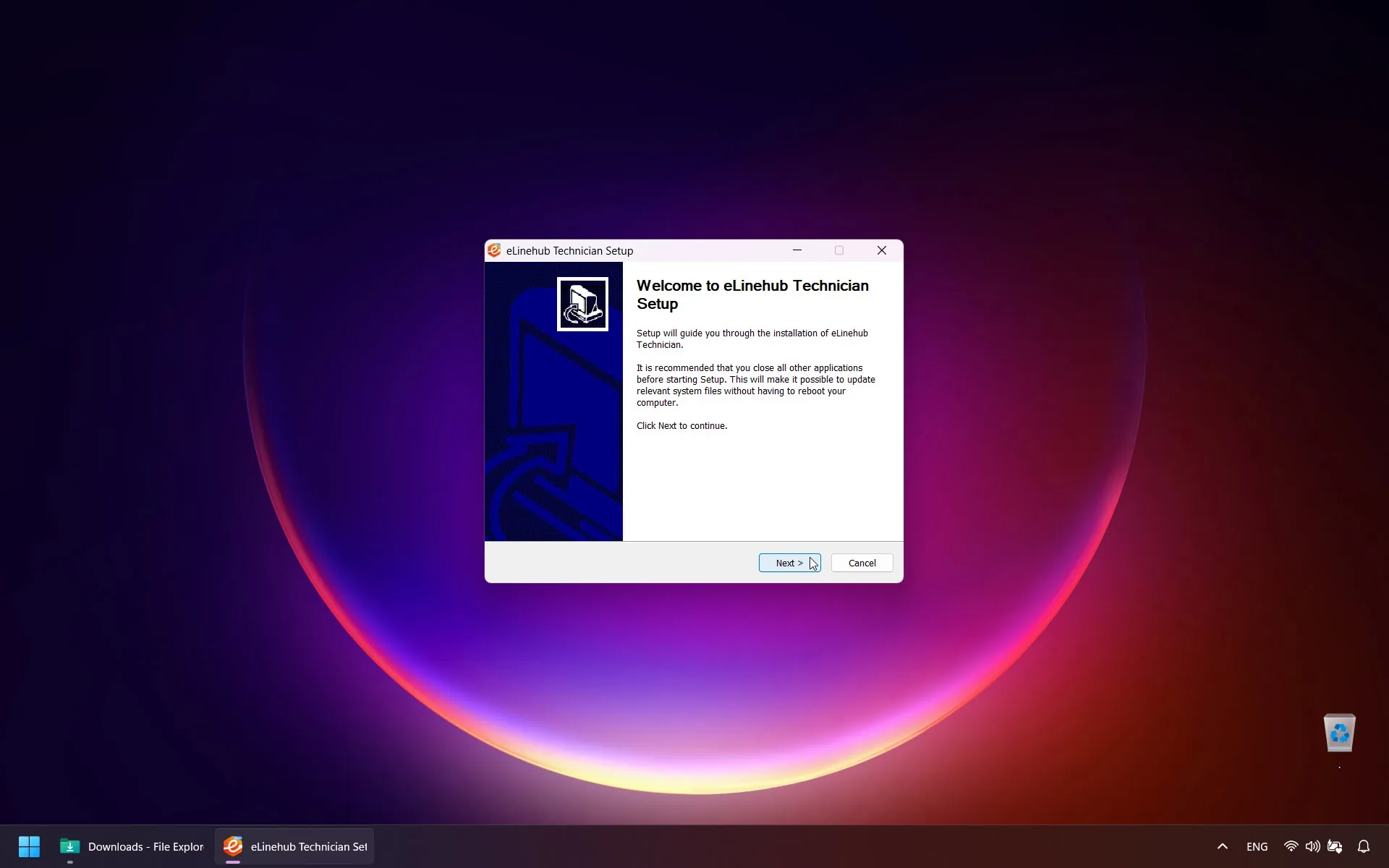
Open your browser and visit the official eLinehub website. Download the latest Technician installer. Once the download completes, run the file and follow the on-screen prompts to finish installation.
Step 2: Create Your Account
When you open the software for the first time, you’ll complete a brief registration:
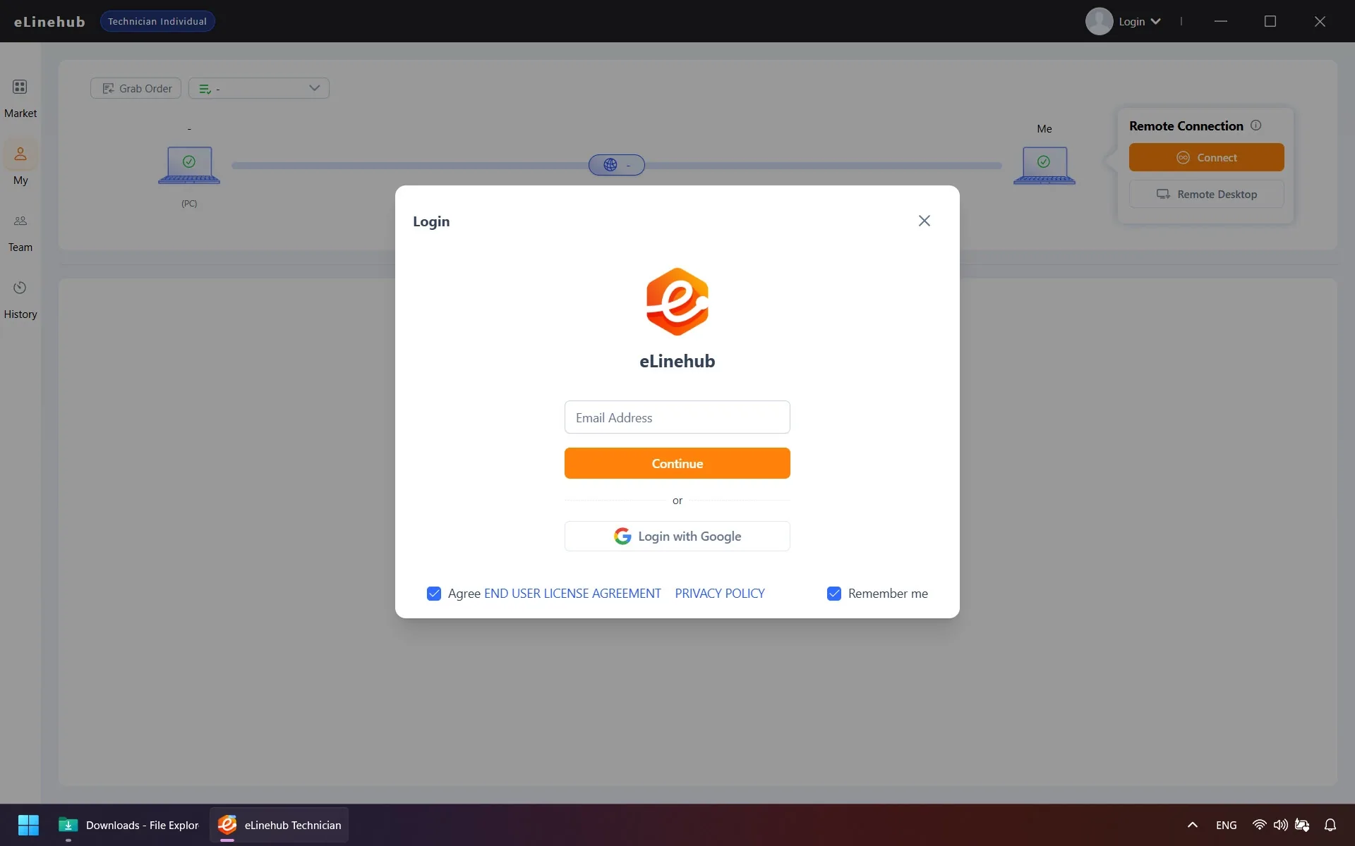
- Enter your email address and click Continue. A six-digit verification code will arrive in your inbox within a few seconds — enter it and submit.
- Fill in your profile details. Select your country first — this setting cannot be changed later. Then choose your state, the car brands you work with, and your certification types.
- Your email is set as your default username, but you can change it and add a profile photo. Review and accept the user agreement, then click Confirm to complete registration.
Step 3: Before You Connect
The checks below cover the most common reasons a connection fails or drops mid-session — complete them on both sides before you begin.
Network Requirements
Both the Technician and Mechanic need a minimum upload speed of 10 Mbps. A wired Ethernet connection is strongly recommended on both ends — especially during ECU programming sessions. DoIP and other Ethernet-based diagnostic protocols enforce strict application-layer communication timing, and wireless connections can introduce variable latency and packet loss that trigger unexpected session drops.
Driver Installation
- Technician side: Install the official driver for the specific VCI model the Mechanic will be using. Without the correct driver, the device will not be recognized on your computer even after a successful connection is established.
- Mechanic side: Standard USB diagnostic devices do not require driver installation. RNDIS-based devices — those that present themselves as a virtual network adapter — require the corresponding driver. If the device type is unclear, install the driver to be safe.
Step 4: Receive Orders and Communicate
eLinehub’s order system keeps vehicle and customer details off any public listing — every order reaches you through one of three direct channels:
The Mechanic generates a unique Passcode when publishing an order. Enter it in the software to claim the job. Only the Technician holding the correct Passcode can accept it — orders cannot be intercepted by other specialists.
Orders submitted through your custom Mechanic build route to your account automatically. No Passcode needed — the Mechanic publishes the job and it appears in your dashboard.
Private orders assigned to your Technician Team appear in your dashboard automatically — no Passcode required.
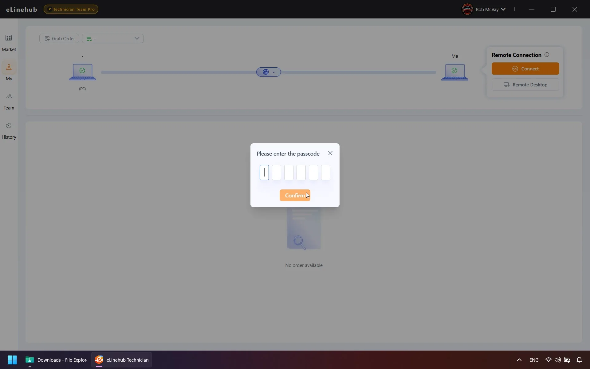
Once you’ve accepted an order, use the built-in Live Chat to discuss vehicle symptoms and service scope with the Mechanic before you begin.
Step 5: Establish the Remote Connection
When the Mechanic marks the order status as Ready, select it to open the connection setup panel. This step walks through four decisions: which device to connect to (5.1), how to bridge it if it’s a network adapter (5.2), which transmission mode to use (5.3), and what to check before launching your diagnostic software (5.4).
5.1 Select the Device
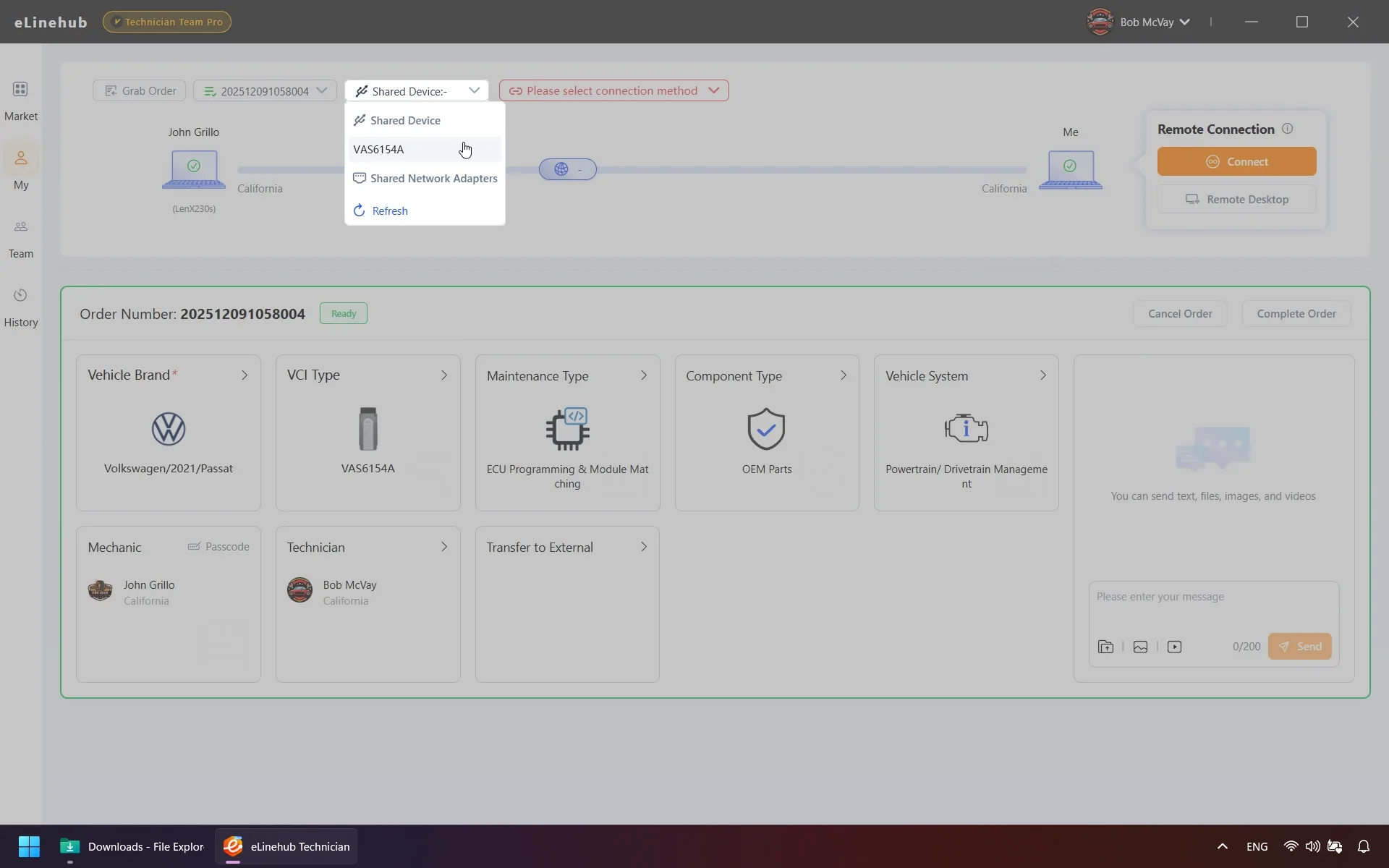
Choose the specific device on the Mechanic’s computer to connect to:
Mechanic USB Connects to a USB-type VCI. Used for traditional CAN, K-Line, and J2534 Pass-Thru devices.
Mechanic Network Adapter Connects to a network adapter on the Mechanic’s machine. Used for DoIP-based VCIs and RNDIS devices.
No Device (Build LAN) Establishes a virtual LAN between both computers without attaching a device. Useful when combined with third-party diagnostic routing software.
If no devices appear in the list, click Refresh. If the target device still doesn’t show up, the software will display a prompt to install the detection plugin — click to install, and it will take effect on both computers simultaneously.
5.2 Configure Bridge Mode (Network Adapter connections only)
If you selected Mechanic Network Adapter, choose how it is bridged to your computer. Select the mode that matches your diagnostic software’s network requirements:
eLinehub Link Bridges the Mechanic’s adapter to a virtual eLinehub Link adapter on your computer. This is the standard choice for most remote diagnostic scenarios, including DoIP workflows. Compatible with ISTA (BMW), XENTRY (Mercedes-Benz), Pathfinder (JLR), and similar OEM platforms. Most diagnostic software discovers network devices automatically — eLinehub Link works with that discovery process directly.
eLinehub vNet Use when your diagnostic software must communicate with a specific local network adapter directly rather than discovering it automatically. After connecting, set your physical NIC to obtain an IP automatically, then assign the fixed IP your diagnostic software expects to the eLinehub vNet adapter.
Physical adapter Bridges the Mechanic’s adapter to one of your physical NICs. Use when your diagnostic software must bind specifically to a physical adapter, or when it runs on a separate computer. After connecting, use a network cable to link the bridged adapter to the appropriate machine.
5.3 Select Transmission Mode
Relay (Recommended) Routes data through an eLinehub relay server. Compatible with all device types — both USB and network adapters. Select the server with the lowest latency from the list.
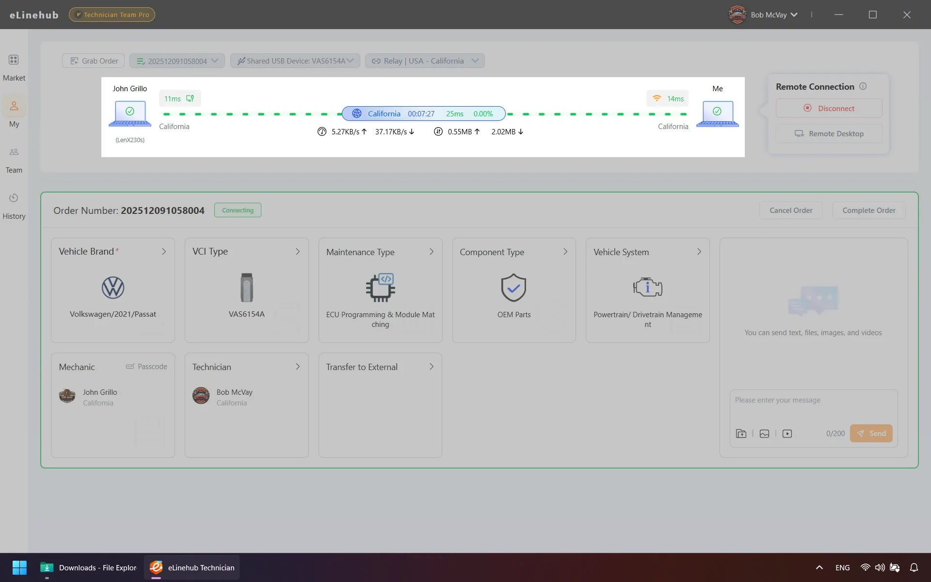
Once the connection is established, the Network Connection Status panel shows live RTT and packet loss for both sides. Confirm both readings meet the requirements for your operation type before launching your diagnostic software:
| Operation type | RTT | Packet loss | Connection |
|---|---|---|---|
| ECU flash / SCN coding / SFD unlock / GeKo (VW Group gateway unlock) | < 50 ms | < 0.5% | Wired, both sides |
| Diagnostics / fault reading / live data / variant coding | < 150 ms | < 1% | Wired recommended |
ECU Programming Session Requirements
Do not begin a programming session if RTT is above 50 ms or packet loss is above 0.5%. A single dropped packet can abort a J2534 URB sequence or invalidate an SFD or GeKo token window mid-operation.
Direct (P2P) Limited to USB-type devices only — network adapter connections require Relay. Establishes a peer-to-peer connection directly between both computers. Typically offers lower latency than Relay. If Relay shows persistently high RTT in your region and you are using a USB VCI, switch to Direct. Wired connections are still recommended on both sides.
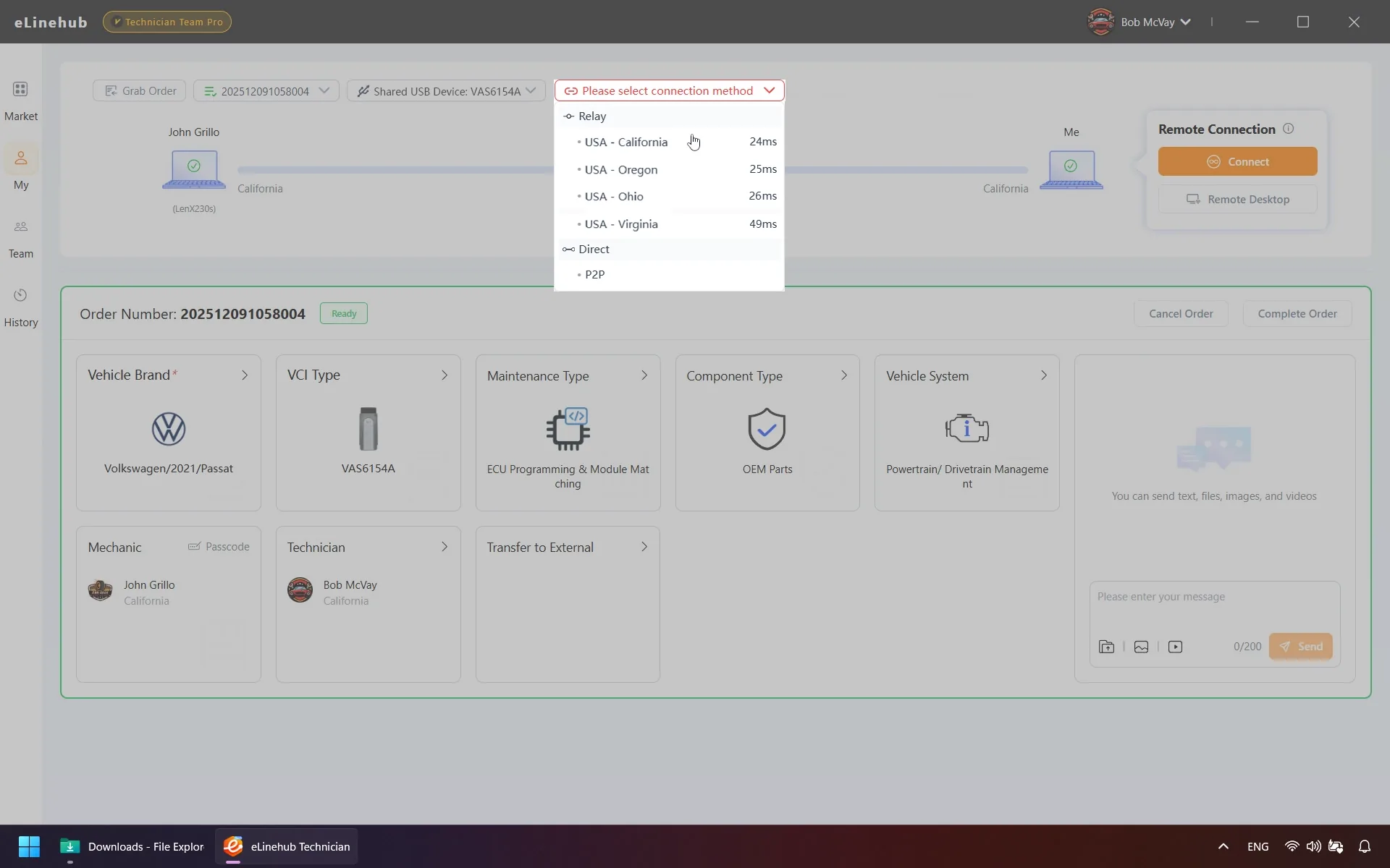
Click Connect to proceed.
5.4 Connection Startup
Once ready, the connection lines between Mechanic PC and Me turn green. The software then displays a live Network Connection Status panel showing the network type (Ethernet, Wi-Fi, or Mobile Hotspot) for both parties, latency, packet loss rate, real-time speed, and total data transferred.
Allow a few seconds after the lines turn green before launching your diagnostic software — this gives the VCI time to complete device initialization on your side. Verify the RTT and packet loss readings from Step 5.3 before opening your OEM software.
5.5 Internet Access Interruption
When the connected VCI or vehicle has an active gateway, your internet access may be interrupted while the diagnostic connection remains fully functional. This is expected behavior caused by routing priority, not a connection failure.
The Switch button in the connection panel toggles between two modes:
- Diagnostic Priority Mode — Optimized routing for vehicle communication.
- Internet Access Mode — Restores normal internet access on your computer.
Do not perform any diagnostic or programming operations while switching, as this causes a brief network interruption. If your diagnostic software behaves abnormally after switching, restart it — or click Switch again to return to Diagnostic Priority Mode.
Step 6: Launch Diagnostic Software
With the connection lines green and the network status panel showing stable readings, you can treat the setup as a local connection.
Open your OEM or professional diagnostic software — ISTA, ODIS, XENTRY, SDD, Pathfinder, or any J2534-compatible application. eLinehub’s USB redirection and network routing layer presents the remote VCI to your operating system as a locally attached device. Your diagnostic software operates with no awareness that the hardware is remote.
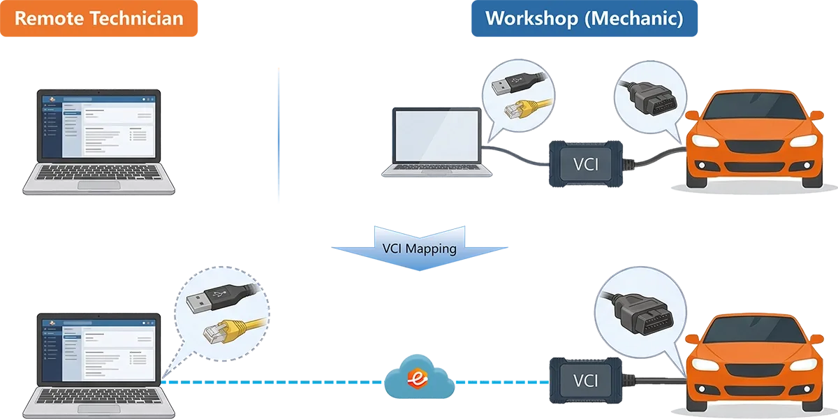
You can now perform all vehicle diagnostics, ECU programming, coding, and adaptation operations exactly as you would with a local setup.
Step 7: Complete the Order
When the session is finished, click Complete Order in the eLinehub software. The Mechanic receives a prompt to review and confirm. If the Mechanic does not respond within the timeout window, the system closes the order automatically.
Once the job moves to Completed status, you can review all past sessions — including vehicle details, operation notes, and duration — under Order History. Billing records for session-based jobs are available in the same view.
New to eLinehub?
Download the Technician software — your first session is free, and no hardware is required on your end to get started.
Download Technician Software → · Share the Mechanic User Guide with your partner →
Troubleshooting
The table below covers the most common issues encountered during setup and active sessions.
| Symptom | Most Likely Cause | Action |
|---|---|---|
| No devices visible in list | Detection plugin not installed | Click the install prompt in the device panel; installs on both sides simultaneously |
| Device listed but won’t connect | VCI driver missing on Technician side | Install the correct OEM driver for the VCI model and reconnect |
| High latency / frequent session drops | Network environment or relay server | Switch to a lower-latency relay server; switch both sides to wired; if USB-only, try Direct (P2P) |
| Connection stuck on “Mapping to Technician side” | Driver conflict or antivirus interference | Restart both computers; temporarily disable antivirus; retry |
| USB mapping failed with Windows error code | Windows driver or hardware conflict | Click the error code to view official Windows guidance; resolve as directed |
| Internet access lost during session | Vehicle or VCI gateway routing conflict | Use the Switch button to toggle between Diagnostic Priority and Internet Access modes |
| Plugin installation fails or conflicts | Conflicting software present on the system | eLinehub will attempt automatic removal; if it fails, manually uninstall the conflicting program, restart, and reconnect |
| ECU flash or SCN coding session aborted mid-operation | RTT or packet loss exceeded threshold at session start | Check live readings in the Network Connection Status panel: RTT must be below 50 ms and packet loss below 0.5% before beginning. Restart only after both readings are stable |
| SFD token window expired before operation completed (Mercedes-Benz) | High latency or connection instability during the token exchange window | Use Relay mode with the geographically closest server; both sides must be on wired Ethernet. If the token expires, request a new one — do not attempt to reuse an expired token |
For issues not covered above, contact the support team at support@elinehub.com.